All Hands on Deck!

This year we’ve reached another milestone for Agile Electronics. Previously we’ve only had a maximum of two people working on electronics assembly at any one time, and that second person has been me (Sandra) since December 2020. This year, we’ve welcomed Hank to be a new casual employee, whose main role is to take on the manual through-hole soldering of boards for our customers. So this week, we’ve had Hank busy soldering and testing boards for one customer, while I was looking after the machines doing surface mount assembly for another customer, and while John inspected boards, supervised everything and helped out where needed.

With our new employee, we will be able to take on more manual soldering, so if this is something your product needs, contact us for a quote.

Unwelcome Trend in Partial Reels

We’ve been pleased to see PCB surface mount assembly customers moving away from supplying cut tape, partly in thanks to our popular article on why cut tape is a bad idea. However, we’ve noticed a trend in recent months, where partial reels suffer a similar problem to cut tape.

A few recent supplies of reeled parts have come on multiple reels, with some reels containing only a single component! There is no point in trying to load a reel with fewer than five components on it onto a pick and place machine (unless the component is large and expensive). Each time a reel is loaded into a feeder and put into position, there is a chance of losing a component or two, despite the care taken by the operator. This is why some assemblers insist on receiving many more parts than required for the boards. (I’ve seen 100 quoted on one assembler’s website.)

While having multiple partial reels is less annoying and costly for assembly than multiple pieces of cut tape, and will lose fewer parts, it will still lead to more parts potentially being lost or unable to be used. It will also mean multiple feeder loadings per component, which will add a few minutes per reel change to the job.

I don’t know what it costs the component wholesaler to put a single component on a reel, given that customers pay a standard fee for reeling, regardless of how many reels are delivered, but I expect that the economics aren’t really there for cheap components. While I sympathise with the goal of avoiding the waste of components, there is waste in the form of extra reels and leader tape, plus time either of workers and/or machines to create the extra reels, not to mention the additional cost downstream during assembly for customers, with components not being used. I hope this trend goes away soon. Meanwhile, I can only advise customers to choose between having fewer boards fully assembled, buying more parts, or using a supplier who doesn’t split ordered components across multiple partial reels.

One for the Silly Season

Greetings all. Here’s this year’s Agile Electronics video for the silly season, The Agile Electronics Alphabet Song. Enjoy!

See you in the new year!

Making sure your circuit board is manufacturable by PCB assemblers

We have seen a variety of board designs presented to us for assembly and have experienced quite a few issues with some of them. Occasionally it makes the board nearly impossible to assemble at all. Here are the absolute minimum requirements for it to be manufactured by machine at all.

  1. The board must fit in the machine. Check the size limitations. If the board is too small, the problem is solved by panelising. If it is too large, you need to either find a different manufacturer that can handle it or try to make your design smaller. We can handle boards between 50mm X 50mm and 250mm x 500mm.
  2. There must be sufficient clearance for the board to be transported through the machine. Any components that are too close to the edge cannot be populated by machine. Either add tooling strips or just keep a good margin along the edge. We recommend 10mm tooling strips to allow for panel fiducials to be located at least 5mm from the edge.
  3. Files are provided to us with the correct data. I will go into more detail elsewhere on this, but we need the centroid data (including for the fiducials) so that the machine knows where to place components and which components to place there. We need the bill of materials that lists components, including their package types so that the machine knows what the component and its pads look like. The gerber files provide other essential information, such as the board’s manufacturability and the orientation of parts.

For more information, contact us for a free copy of our tips on design for manufacture.

Twelve Days of DFM Feedback from Agile Electronics

Agile now has a Youtube channel! We probably will still mostly use the blog for information. But for now, find our twelve days of feedback for the season. Entertaining and useful at the same time. Enjoy!

Robotic carollers

Through-hole versus Surface Mount

Many older electronic designs use through-hole components, which are usually manually placed onto circuit boards before they can be soldered. While some components are best kept as through-hole, such as connectors, most can be replaced with surface mount equivalents. Let’s look at why this might be a good idea.

When we work with through-hole components, the following happens for larger jobs:

  1. Manually place the through-hole components
  2. Use our wave solderer to solder all the through-hole components on the board
  3. Clean the boards

The wave solderer itself has an associated set-up and clean-up cost as well. (Note: some manufacturers use “selective soldering” for this task, which has a few advantages over wave soldering.) For small jobs it is usually cheaper and easier to manually solder the through-hole components. However, labour is not very cheap compared to machines.

On the other hand, for surface-mount components provided on a reel, we load the reel into a feeder element, mount the element in the feeder trolley and program the feeder. Then the pick and place machine does the rest. Once again, there is a set-up cost associated with each type of component, but if you are wanting hundreds of boards or more, surface mount components are the way to go.

Components on a reel, loaded onto a feeder element
Component feeders in a feeder trolley

The power of the panel

The next episode in our series on getting the best value out of your surface mount assembler is panelising. The surface mount assembly process involves three main steps for each board (or panel):

  1. solder pasting
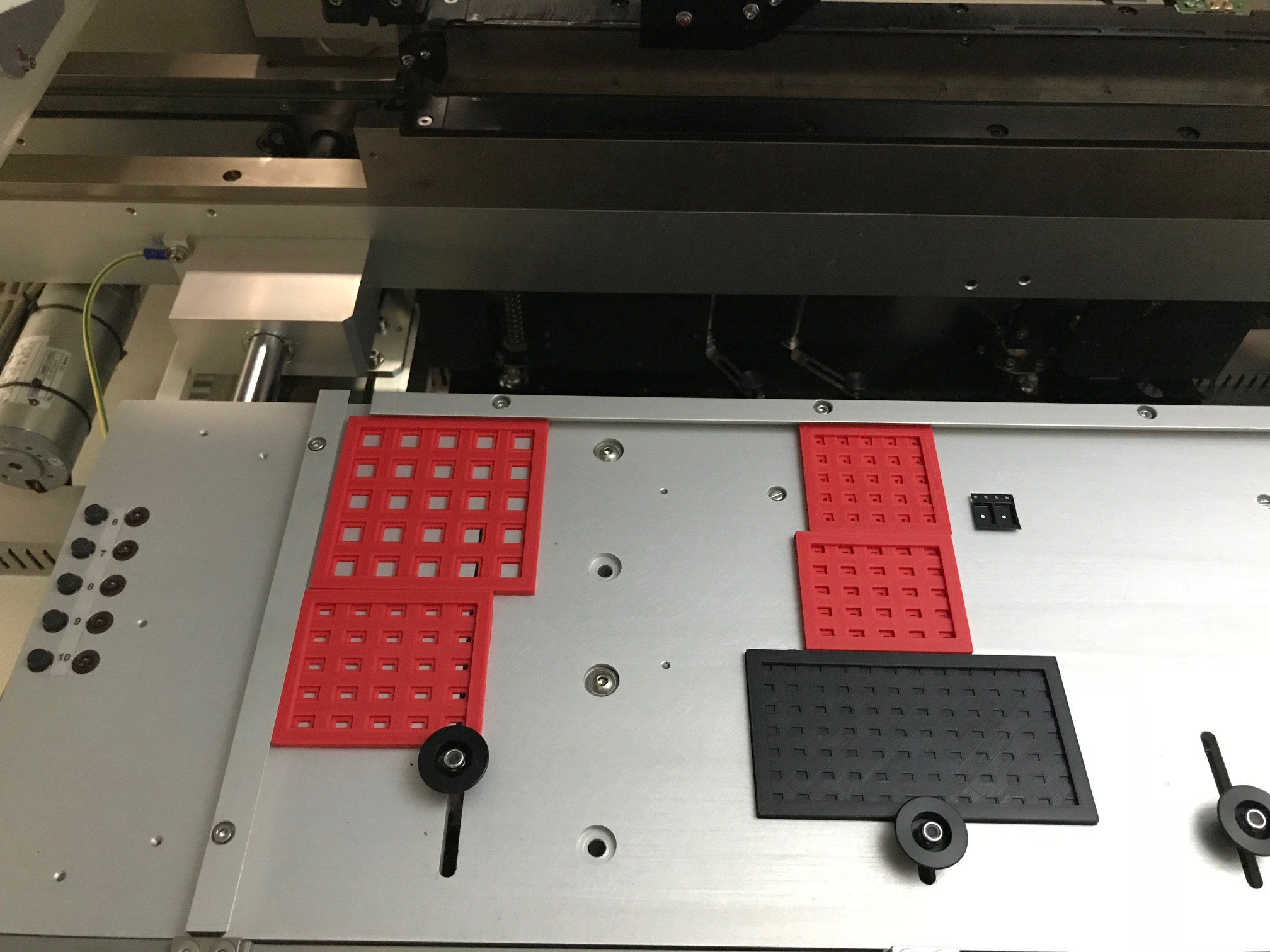
  2. placing surface mount components on the board using the pick and place machine
  3. melting the solder in a reflow oven

Each of these stages is faster if you have the maximum number of boards possible within a single panel. Suppose it is possible to have ten boards in a single panel. That can make solder pasting ten times faster.

Some gains are also possible with the pick and place machine stage, if a board takes less than a minute to populate, there could be a delay between putting it into the machine and moving to the reflow stage. The pick and place machine itself will place components more efficiently if populating an entire panel of boards instead of individual boards, since there will be fewer nozzle changes needed.

Depending on the reflow set-up, panelisation can make things much faster or just a little. If the reflow oven is automated, taking boards that exit the pick and place machine, the speed increase may be a multiple of one dimension of the panelised board. For ovens with manual input, panelisation will greatly reduce the handling required. Imagine the relative effort of carefully placing 10 boards in an oven versus one. The operator needs to be careful to avoid touching the solder paste, as well as making sure that the board is level and not jerked about, or components will be dislodged. It’s a bit like a waiter bringing a full bowl of soup to a diner.

Panelising may also provide savings at later stages, for example, if the boards need to be cleaned, then this will be faster if an entire panel can be cleaned at once.

In some cases, a board must be panelised, for example, if it is too small to be populated by the machine. The Europlacer XPii requires the board to be at least 50mm by 50mm. It must also have two parallel sides with 5mm clearance to allow it to be held by the machine.

Not all manufacturers work the same way. The degree of automation will differ. Pick and place machines vary in their capabilities. So the exact savings will differ. But as a very rough guide, if  your board is very small, has an unusual shape, or you need at least 40 boards and can fit at least 4 boards in a panel, it is likely to be worth panelising.

Many Changes Afoot for Agile

2020 – what a year! During the pandemic we bought new premises for the business. We’re still setting up, but the new address is 174-176 Through Rd, Camberwell.

We also have new machinery, in the shape of a Dek solder printer. Stay tuned for more news.

Is there anything worse than cut tape? Sadly, yes.

Previously I wrote about how providing your components on cut tape slows the SMT assembly process for the assembler, because they need to mount your tape on a reel before putting the reel on the feeder.

There is one thing worse than cut tape, and that is loose components! You might think it is a saving to just buy a bag of the components you need, but if you are using a professional assembler, it is often cheaper to buy in bulk on a reel, or to make use of the very reasonable reeling service from suppliers like Digikey or Mouser, where your small number of components are mounted on a reel, ready for assembly.

So, what do we do when we receive loose components? Some are taken out of their plastic bags and put into a belt or tube feeder. For others, we need to design and print a special matrix tray, and then manually place the components into the matrix tray. For really short cut tape, we stick the tape into the matrix tray area with removable double-sided tape. For each tray or short cut tape, the pick and place machine needs to be programmed to indicate the dimensions of the tray and the type of component contained in it. As you can imagine all this preprocessing takes quite a bit of time. So, do think twice about how you provide components to your friendly assembler!

matrix1
Custom matrix trays set up in the Europlacer pick and place machine. Also a short piece of cut tape with only two components, stuck into the matrix tray area.


Seven years of electronics assembly

Seven years ago today we received our first pick and place machine, a Novastar. Since then we’ve upgraded to a high-speed Europlacer XPii that can handle smaller components. This month we have acquired an Exmore VS-500 vapour phase reflow oven. With the addition of this unit, we can achieve a more even temperature across circuit boards, regardless of the uneven thermal mass of some designs, meaning fewer tombstone errors on assembled boards.

vapourphasereflowoven_open
Our new Vapour Phase Reflow Oven.